Flight Modes Setup
The Flight Modes section allows you to map flight modes to radio channel(s), and hence to the switches on your radio control transmitter. Both flight mode setup and the available flight modes are different in PX4 and ArduPilot (and there are some differences between ArduCopter and ArduPlane).
INFO
In order to set up flight modes you must already have already configured your radio, and setup the transmitter (as shown below).
To access this section, select the Gear icon (Vehicle Setup) in the top toolbar and then Flight Modes in the sidebar.
For more flight stack specific setup see:
Transmitter Setup
In order setup flight modes you will first need to configure your transmitter to encode the physical positions of your mode switch(es) into a single channel.
On both PX4 and ArduPilot you can assign up to 6 different flight modes to a single channel of your transmitter It is common to use the positions of a 2- and a 3-position switch on the transmitter to represent the 6 flight modes. Each combination of switches is then encoded as a particular PWM value that will be sent on a single channel.
INFO
The single channel is selectable on PX4 and ArduPlane, but is fixed to channel 5 on Copter.
The process for this varies depending on the transmitter. A number of setup examples are provided below.
Taranis
These examples show several configurations for the FrSky Taranis transmitter.
Map 3-way Switch to a Single Channel
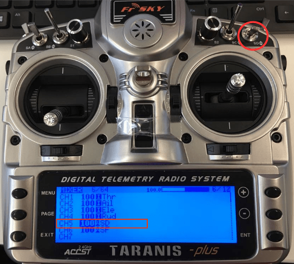
If you only need to support selecting between two or three modes then you can map the modes to the positions just one 3-way switch. Below we show how to map the Taranis 3-way "SD" switch to channel 5.
Open the Taranis UI MIXER page and scroll down to CH5, as shown below:

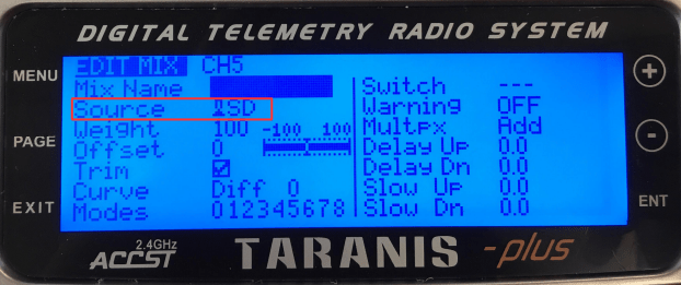
Press ENT(ER) to edit the CH5 configuration then change the Source to be the SD button.

That's it! Channel 5 will now output 3 different PWM values for the three different SD switch positions.
Map Multiple Switches to a Single Channel
Most transmitters do not have 6-way switches, so if you need to be able to support more modes than the number of switch positions available (up to 6) then you will have to represent them using multiple switches. Commonly this is done by encoding the positions of a 2- and a 3-position switch into a single channel, so that each switch position combination results in a different PWM value.
On the FrSky Taranis this process involves assigning a "logical switch" to each combination of positions of the two real switches. Each logical switch is then assigned to a different PWM value on the same channel.
This video shows how this is done with the FrSky Taranis transmitter: https://youtu.be/TFEjEQZqdVA